Background
eVOLVER hardware is primarily divided between the Smart Sleeves and Motherboard. The Motherboard is where all the sensitive control hardware is, whereas the Smart Sleeve is nice modular way of integrating all the sensors to control your culture conditions.
Goal
The goal of this tutorial is to show how one can build an eVOLVER Smart Sleeve using commonly found tools and easily customizable parts.
How long does it take to typically build a Smart Sleeve and how much does it cost?
In this post, we are describing the Smart Sleeve built for continuous culture documented in our Nature Biotechnology paper. It typically takes 10 to 15 minutes for construction of this version of the Smart Sleeve with all the appropriate parts (e.g. soldered PCB, constructed aluminum tube). Raw materials cost roughly $40/ vial however cost for 3D printing, machining, and coloring (spray painting/ anodizing) parts vary due to accessibility to appropriate tools.
That sounds all great, but I have never soldered or 3D printed before, how do I start?
Here is a great introductory tutorial on soldering from our friends at Sparkfun. Also, you can easily outsource your 3D printed parts to be produced by folks at 3DHubs by uploading the appropriate STL file (if you're a student, don't forget the student discount!). Generally, building a Smart Sleeve is simple because we only use through hole components and screw terminals, so it is much easier to make than surface mount designs.
How can I modify or change the design?
We built our PCB designs on KiCAD, an open-sourced software for circuit board design, and our 3D models on Solidworks. Here is a schematic of the PCB here and the Solidworks part here. There are many other programs for vial board design, including a bunch of tutorials on Eagle from Sparkfun, another popular CAD tool for the open-source community.
Does this tutorial include how to build the Motherboard?
No. This tutorial only provides instructions on how to build a Smart Sleeve.
Let's get started!
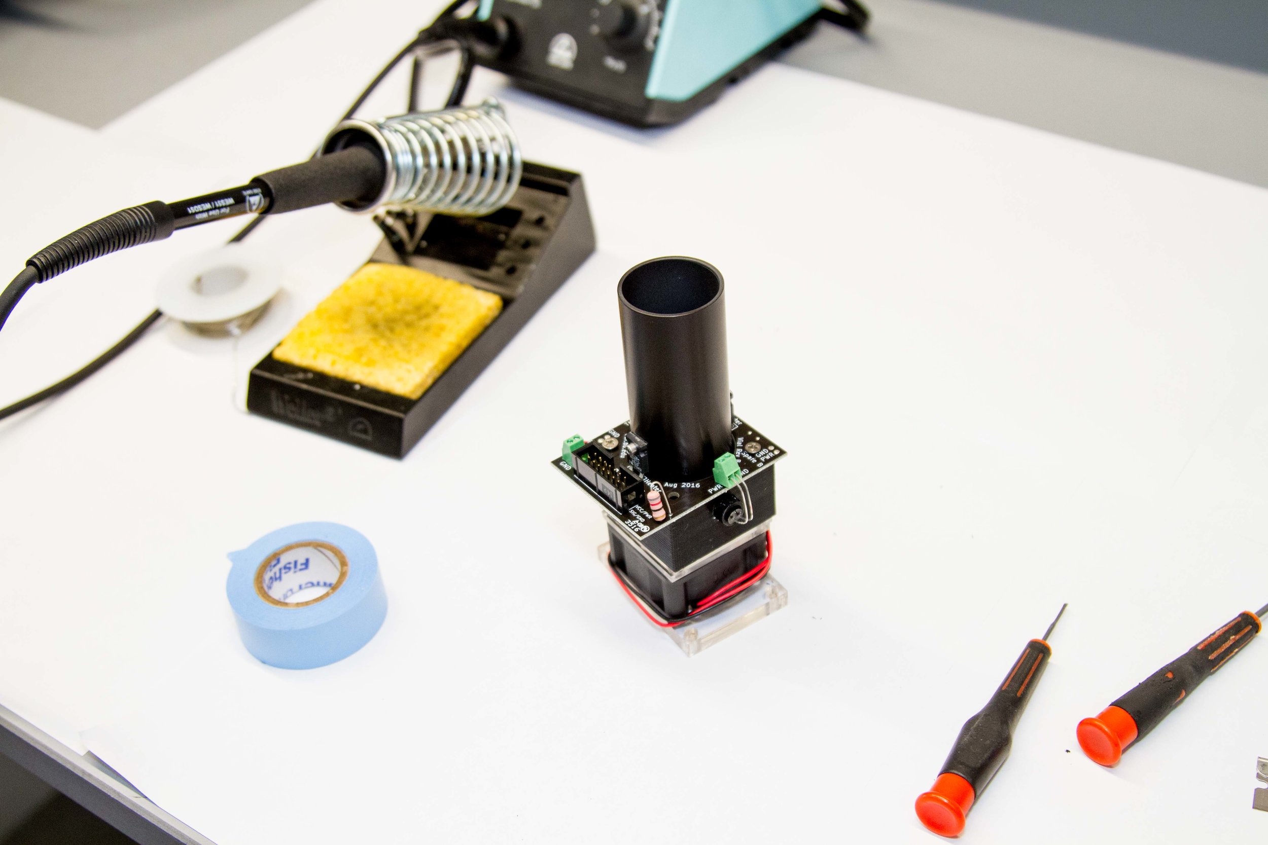
1. Order all the necessary parts and tools necessary.

List of supplies needed (displayed in photograph above):
- Laser Cut 1/4" Acrylic Base
- 2 pieces of laser cut 1/8" Acrylic Fan Spacers
- 5/64" Hex Key
- IR LED
- IR Photodiode
- Thermistor
- 2x Socket head screw
- 12 V DC Computer Fan with Magnets Glued
- Vial Board
- Lab Tape
- 3D Printed Part
- Aluminum Tube
- Soldering Iron + Solder
- 2x Stainless Steel Screws, 2.5" 4-40 threading (Not Shown)
2. Familiarize yourself with how the Vial Board, 3D printed part, and aluminum tube should be assembled.
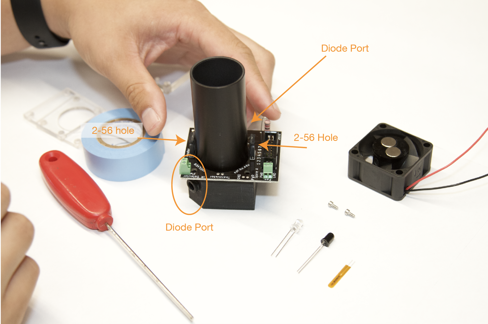
Take notice if all the components line up properly:
- Tapped 2-56 holes on the Aluminum Tube lines up with holes on heating resistors (2 black rectangular components soldered on vial board)
- The heating resistors should sit on two rectangular holes on the 3D printed part
- Green screw terminals line up with the LED holes on the 3D printed part
Take note of where the two holes labeled "thermistor" are on the PCB.
3. Tape thermistor on the aluminum tube near where the two vias were located on the PCB.

When taping the thermistor, ensure the writing on the thermistor is facing away from the aluminum tube. Tape the thermistor parallel to the length of the tube about .5 cm away from the bottom of the tube. The leads should be exposed when slotted into the 3D printed part.
3. Slot the aluminum tube into the 3D printed part. Verify that the holes for the LEDs on both the aluminum tube and 3D printed part are properly aligned.

Make sure 3D printed part is slotted tightly. Add additional pieces of tape if is loose. Avoid damaging the thermistor by twisting or rotating the parts.
4. Align the PCB over the 3D printed part, with the two thermistor leads threading through the vias on the PCB.

Also verify that the two small 2-56 holes on the aluminum sleeve align with the holes on the heating resistor.
5. Use the 2x Socket head screws to fasten the heating resistors to the aluminum sleeve.
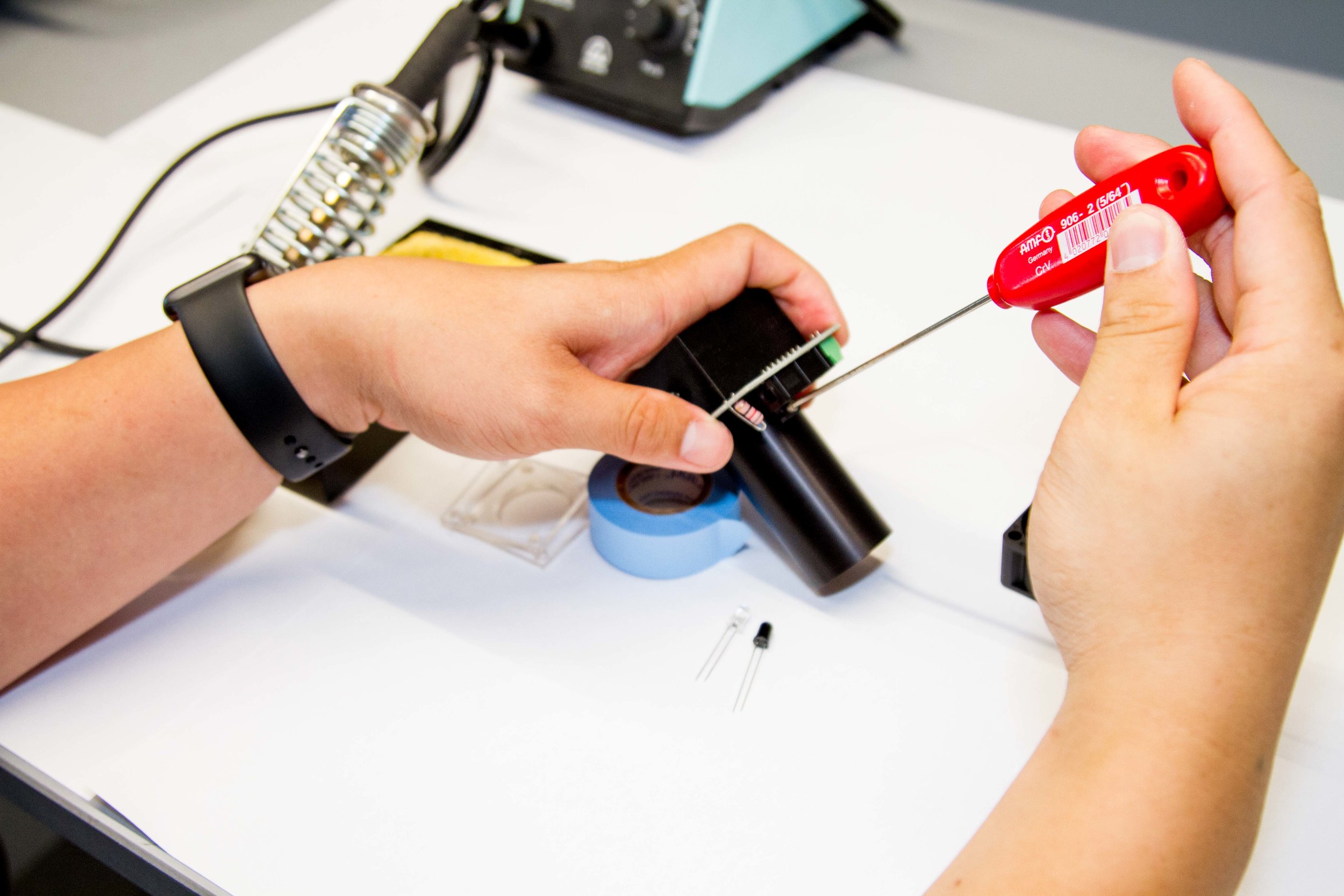
Aligning the hole with the heating resistor makes screwing the socket cap in much easier. Thermal paste can also be applied before this step to form better contact between the heaters and aluminum tube.
6. Place the 1/8" laser cut acrylic pieces onto of the fan to act as spacers between the magnets and glass vessel.

7. Use the two 4-40 stainless steel screws to fasten the assembled 3D printed part and the computer fan with spacers. Fasten both screws onto the 1/4" acrylic piece.


8. Coil the wires from the computer fan around the Smart Sleeve and connect to appropriate ports on the screw terminal labeled "fan".
The red wire should go into PWR and the black wire should go into the GND ports.
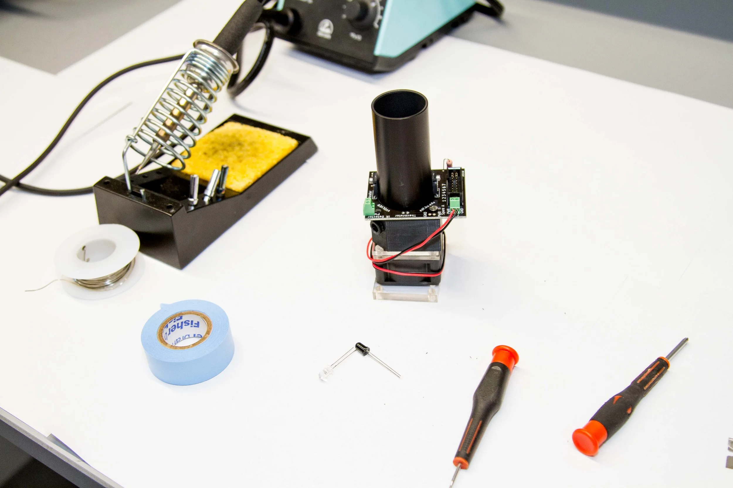
9. Attach the LED (clear packaging) and photodiode (dark packaging) for OD measurement to the appropriately labeled slots.

Both the photodiode and LED should have a short and a long lead. This corresponds to the polarity of components. Make sure for both components, the longer lead is connected to PWR. If this is done improperly, you will not get a reliable signal.
10. Bend the LED and diode into the corresponding slots.
11. Finally, solder the thermistor onto the PCB.
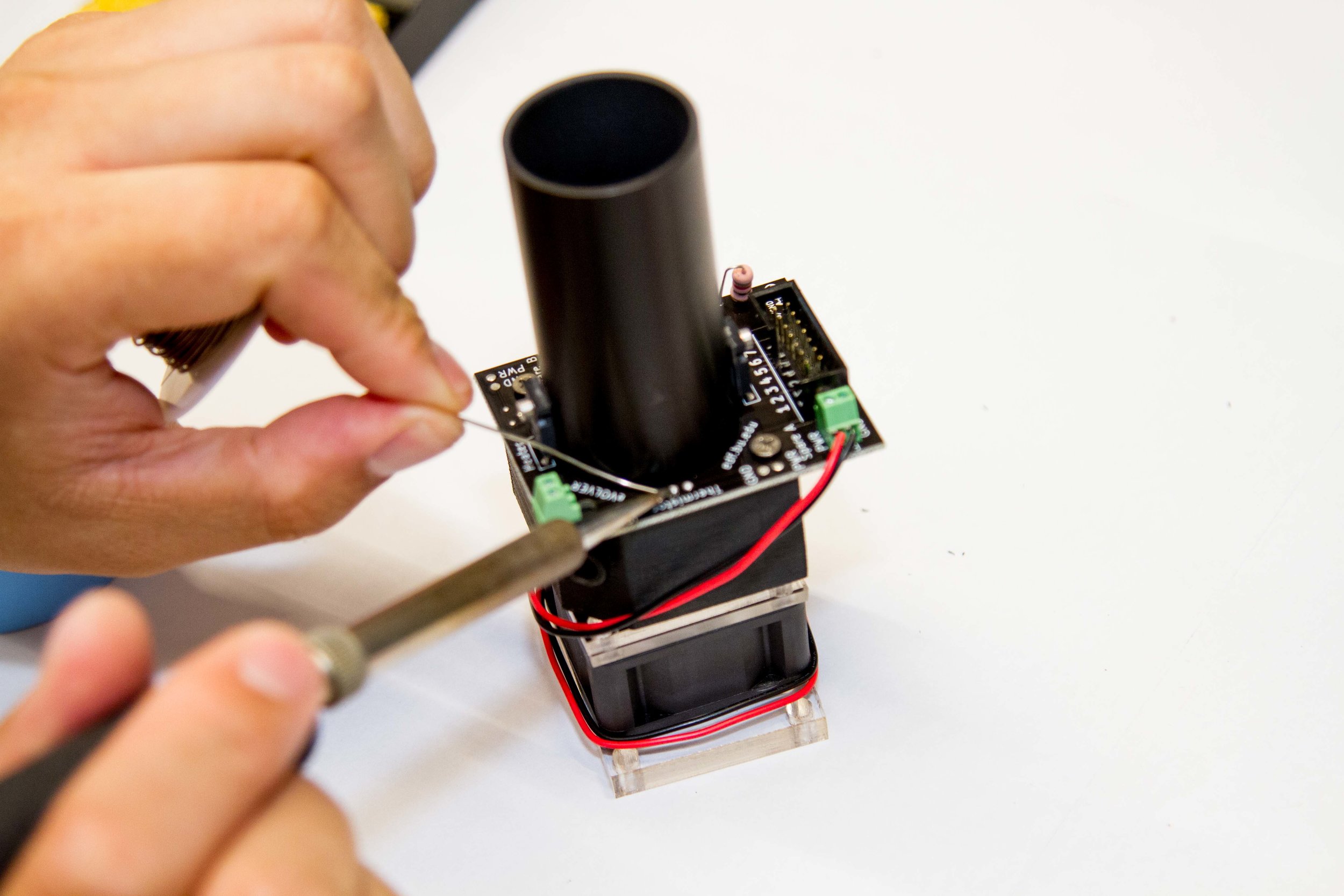
That's it! You're done.
Following a similar framework for building the Smart Sleeves enables adding different parameters, adaptation to different vial sizes, and other creative eVOLVER applications! Have fun! Let me know if anything is unclear.